GEO-PHYSICAL SURVEYING SERVICES
Geophysical Testing
A variety of geophysical methods (non-destructive test methods) can be used to have a comprehensive understanding of the subsurface conditions at a site, allowing for coverage of a much larger region than is possible with traditional destructive testing methods.
Falcon Lab’s professional engineers use geophysical surveying services to decide whether there are any irregularities or anomalies in the background readings by analyzing the geophysics properties of the earth.
Geophysical surveying is the use of geophysical methods to gather information about the subsurface of the earth.
Geophysical surveying is used in a variety of applications, It helps in identifying subsurface features and anomalies, providing valuable information for decision making and reducing exploration risk.
These anomalies can indicate the existence of underground hazards such as utilities, buried tanks, sinkholes, or old landfill material if properly interpreted. Geophysical services are often used to determine the rock’s surface and classify seismic sites.
Geophysics services involve the application of physics and geology principles to explore and study the earth’s subsurface. Geophysical services helps in reducing uncertainty in the exploration and development of natural resources, making it a crucial aspect of the energy and mining industries.
Geophysical techniques we utilize include
- MASW (Multi Channel Analysis of Surface Waves)
- Seismic Cross Hole Test
- Seismic Down Hole Test
- Electrical Resistivity Tomography
- Ground Penetrating Radar (GPR)
1. MASW (Multi Channel Analysis of Surface Waves)
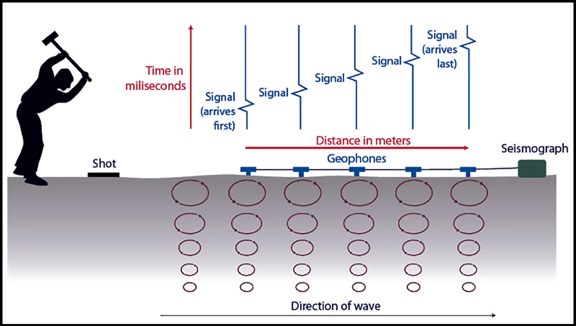
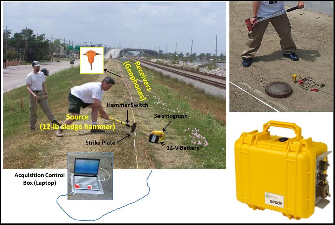
MASW is a seismic tool for determining the shear-wave velocity distribution, which can be used to determine the overburden and bedrock arrangement. It examines how surface waves disperse (usually the fundamental-mode Rayleigh waves). An array of geophones, similar to other seismic methods, is used to detect seismic waves. Surface waves for MASW can be produced using an active source such as a sledgehammer. The shear wave (Vs) profile is given in one of two formats: 1D (depth) or 2D (depth and surface distance). The results can be used to evaluate soil and rock strength (stiffness), map subsurface geology (lateral and vertical variations), map low velocity layers, determine IBC Vs100 (Vs30) site classification.
SEISMIC SHEAR WAVE VELOCITY MEASUREMENTS UTILIZING MASW
MASW is a seismic method that uses the dispersive nature of surface waves to map the values of shear wave velocities (Vs) in the subsurface. Shear wave velocity is a function of the elastic properties of the soil and rock and is directly related to the hardness (N-values) and stiffness of the materials. In particular, MASW is used in geotechnical for the measurement of shear-wave velocity and dynamic properties, identification of subsurface material boundaries and spatial variations of shear-wave velocity for site classification..
In geotechnical engineering, MASW is used for shear-wave velocity measurement, identification of subsurface material boundaries, and spatial variations of shear-wave velocity for site classification.
Applications:
- Map soil and sediment thickness, subsurface interfaces, and stiffness.
- Determine shear wave velocity or density of subsurface material, detect voids and karst features.
- Site classification.
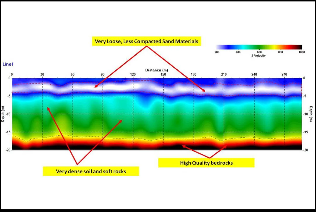
Examples:
Shear wave velocity (Vs) map obtained from active MASW. Very strong near-surface shear-wave velocity contrasts indicate loose fill materials and fractured bedrocks.
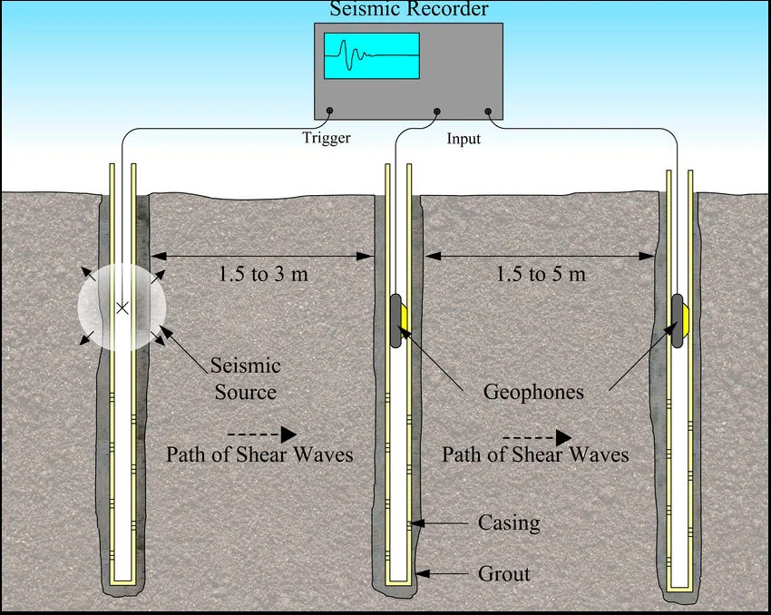
2. Seismic Cross Hole Test
The seismic cross-hole geophysical tests provide measurements of the propagation times of longitudinal elastic waves (p waves) and shear waves (s waves) between two or more boreholes along direct trajectories at different depths.The trend along the depth of the seismic wave velocities and the elastic parameters characteristic of the material being investigated can be described by the travel times and the distance between the measurement points. When the time of arrival of the seismic waves has been determined and the distance between these two points has been determined the velocities of the compressional (vp) and transverse (vs) waves are calculated, and the transmitter and receiver boreholes are known (obtained by inclinometric survey).
The results are diagrams of velocity and depth. The poisson’s ratio, the average material density, and the dynamic elastic modules ED and GD can all be calculated from the vp and vs velocities (elastic modulus and cutting module). This form of investigation is also suitable for different transmitter and receiver configurations on site, and can therefore be processed by specific 2D scanners.This kind of investigation is also suitable for different transmitter and receiver configurations on site, and thus for tomographic results to be processed by specific 2D software.
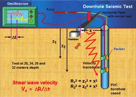
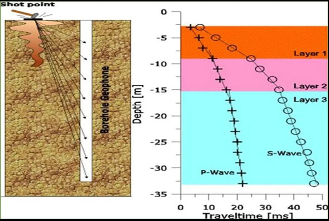
3. Seismic Down Hole Test
The propagation velocities of p waves and s waves in materials crossed by a single hole are determined using the down-hole technique. The travel times that elastic pulses (p and s waves) produced at the surface near the borehole employ to reach one or more geophones in the borehole at different depths are measured in the Testing Process. Velocities are calculated as the ratio of the difference in the recorded times and the difference in the paths, related to a range of depths. During each measurement, the receiver contains three part geophones (2 horizontals and one vertical) that are firmly clamped to the borehole wall.
The seismic trigger is normally surface hammering. By obtaining two shear wave records striking the plank in opposite directions horizontally As a result, the shear wave reports. The polarity of the results has been reversed. The P-wave record is obtained by measuring the P-wave produced by striking the ground with a sledge hammer. The compression and shear wave velocities can be calculated using the P-wave and S-wave records. The interval velocity is calculated by dividing the distance between the geophone locations by the arrival times difference. Following that, it’s plotted as a function of depth. As a result, the elastic properties of the encountered layers can be measured up to the borehole’s necessary depth (30m). The seismic Downhole method provides a designer with information pertinent to the seismic wave velocities of the materials). The P-wave and S-wave velocities are directly related to the important geotechnical elastic constants of Poisson’s ratio, shear modulus, bulk modulus, and Young’s modulus. Accurate in-situ P-wave and S-wave velocity profiles are essential in geotechnical foundation designs. These parameters are used in both analyses of soil behaviour under both static and dynamic loads where the elastic constants are input variables into the models defining the different states of deformations such as elastic, elastic-plastic, and failure. Another important use of estimated shear wave velocities in geotechnical design is in the liquefaction assessment of soils.
The Downhole Test is a method which determines soil stiffness properties by analysing direct compressional and shear waves along a borehole down to about 30 m. The aim of the downhole testing is to derive elastic rock properties such as Poisson’s ratio or Young’s modulus. Shear waves have to be generated at surface. A shear wave source (sledge hammer hit sidewise) is used at surface and a coupled receiver system is moved in the borehole. Travel times of the seismic waves are analysed and seismic velocity is calculated. Shear wave velocity can be transformed to soil stiffness. The measurements can be performed below and above the groundwater table. A grouted casing (e.g. PVC) with a diameter between 3 and 3.45 inch needs to be prepared.
The Downhole test requires a surface source capable to generate S- and P-waves and a borehole receiver with a multi-directional sensor array. S- and P-wave velocities are measured and the dynamic soil parameters (shear and Young’s modulus) are calculated, sledge hammer (equipped with a trigger element) and a wooden beam can serve as source if the survey depth is limited.
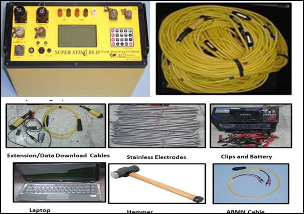
4. Electrical Resistivity Tomography (ERT)
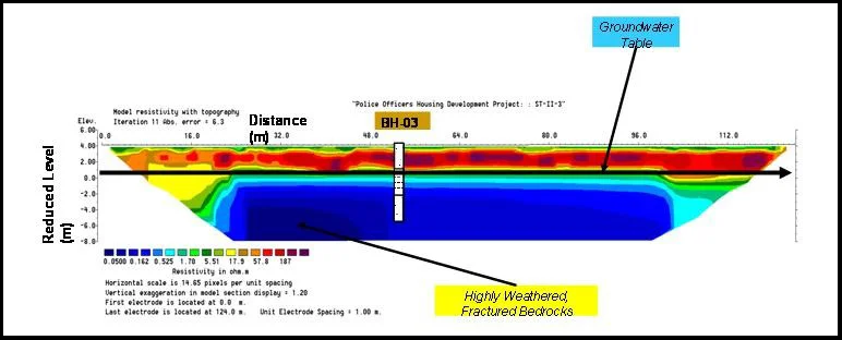
Electrical Resistivity Tomography (ERT) is a sophisticated geophysics technique that uses ground surface measurements to assess the subsurface resistivity distribution. An automatic multi-electrode resistivity meter is used to collect ERT data quickly. A modeled cross-sectional (2-D) plot of resistivity (Ω•m) versus depth makes up ERT profiles. The geometry, lithology, hydrology, and/or petrology of subsurface geologic formations are accurately represented by ERT interpretations, which are confirmed by borehole data or alternative geophysical data.
Resistivity geophysical surveys measure variations in the electrical resistivity of the ground, the idea of ERT technique is to pass a current of known voltage into the subsurface to be imaged through two current electrodes, and then using a second pair of potential electrodes, measure the potential drop induced by the differential response of earth materials to the penetrating current. The survey data will be processed to produce graphic depth sections of the thickness and resistivity of subsurface electrical layers. The resistivity sections are correlated with ground interfaces such as soil and fill layers or soil-bedrock interfaces, to provide engineers with detailed information on subsurface ground conditions
Applications:
- Measure bedrock & water table depth
- Detect cavities, voids, and karst features
- Locate buried alluvial channels
- Identify weathered/fractured bedrock
- Map leachate contamination & saline groundwater
- Find abandoned mineshafts & workings
Examples:
2D Electrical Resistivity Inverted Section
QUICK CONTACT
OUR SERVICES
ASK AN EXPERT TO CONTACT YOU
Looking for Geophysical Survey Services for your Company?
Schedule an Appointment with our Experts Team Today
ABU DHABI LOCATION
Falcon Laboratory LLC
Store No 1, Plot No 08, Mussafah 32/1,
P.O. Box: 113765,
Abu Dhabi, United Arab Emirates
- 24°21'10.2"N 54°30'45.8"E

DUBAI LOCATION
Falcon Laboratory LLC
Near Dubai Municipality Nursery
Al Warsan Third,
P.O. Box: 231494,
Dubai, United Arab Emirates
- 25°09'27.9"N 55°27'42.6"E
SHARJAH LOCATION
Falcon Laboratory LLC
Al Oufouk B Block, Shop No : 02
Industrial Area 17,
Maleha Road Back Side
Post Box: 71713
Sharjah, United Arab Emirates
- 25°17'13.1"N 55°26'44.7"E